
Compressed air is used to operate pneumatic systems in a
facility, and it can be segregated into three sections; the supply side, the
demand side, and the distribution system. The supply side is the air
compressor, after-cooler, dryer, and receiver tank that produce and treat the
compressed air. They are generally located in a compressor room
somewhere in the corner of the plant. The demand side are the
collection of end-use devices that will use the compressed air to do “work”.
These pneumatic components are generally scattered throughout the
facility. To connect the supply side to the demand side, a compressed
air distribution system is required. Distribution systems are pipes
which carry the compressed air from the compressor to the pneumatic
devices. For a sound compressed air system, the three sections have to
work together to make an effective and efficient system.
An analogy, I like to compare to the compressed air system, is
an electrical system. The air compressor will be considered the voltage
source, and the pneumatic devices will be marked as light bulbs. To
connect the light bulbs to the voltage source, electrical wires are
needed. The distribution system will represent the electrical
wires. If the wire gauge is too small to supply the light bulbs, the
wire will heat up and the voltage will drop. This heat is given off as
wasted energy, and the light bulbs will dim.
The same thing happens within a compressed air system.
If the piping size is too small, a pressure drop will occur. This is
also wasted energy. In both types of systems, wasted energy is
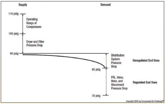
wasted money. One of the largest systematic problems with compressed
air systems is pressure drop. If too large of a pressure loss occurs,
the pneumatic equipment will not have enough power to operate
effectively. As shown in the illustration below, you can see how the
pressure decreases from the supply side to the demand side. With a
properly designed distribution system, energy can be saved, and in reference
to my analogy, it will keep the lights on.
To optimize the compressed air system, we need to reduce the
amount of wasted energy; pressure drop. Pressure drop is based on
restrictions, obstructions, and piping surface. If we evaluate each
one, a properly designed distribution system can limit the unnecessary
problems that can rob the “power” from your pneumatic equipment.
1.
Restriction:
This is the most common type of pressure drop. The air flow is forced into
small areas, causing high velocities. The high velocity creates
turbulent flow which increases the losses in air pressure. Flow within
the pipe is directly related to the velocity times the square of the
diameter. So, if you cut the I.D. of the pipe by one-half, the flow
rating will be reduced to 25% of the original rating; or the velocity will
increase by four times. Restriction can come in different forms like
small diameter pipes or tubing; restrictive fittings like quick disconnects
and needle valves, and undersized filters and regulators.
2.
Obstruction:
This is generally caused by the type of fittings that are used. To help
reduce additional pressure drops use sweeping elbows and 45-degree fittings
instead of 90 deg. elbows. Another option is to use full flow ball
valves and butterfly valves instead of seated valves and needle valves.
If a blocking valve or cap is used for future expansion, try and extend the
pipe an additional 10 times the diameter of the pipe to help remove any
turbulence caused from air flow disruptions. Removing sharp turns and
abrupt stops will keep the velocity in a more laminar state.
3.
Roughness:
With long runs of pipe, the piping surface can affect the compressed air
stream. As an example, carbon steel piping has a relative rough
texture. But, over time, the surface will start to rust creating even a
rougher surface. This roughness will restrain the flow, creating the
pressure to drop. Aluminum and stainless steel tubing have much
smoother surfaces and are not as susceptible to pressure drops caused by
roughness or corrosion.
As a rule, air velocities will determine the correct pipe
size. It is beneficial to oversize the pipe to accommodate for any
expansions in the future. For header pipes, the velocities should not
be more than 20 feet/min (6 meter/min). For the distribution lines, the
velocities should not exceed 30 feet/min (9 meter/min). In following
these simple rules, the distribution system can effectively supply the
necessary compressed air from the supply side to the demand side.
To have a properly designed distribution system, the pressure
drop should be less than 10% from the reservoir tank to the
point-of-use. By following the tips above, you can reach that goal and
have the supply side, demand side, and distribution system working at peak
efficiency. If you would like to reduce waste even more, EXAIR offers a
variety of efficient, safe, and effective compressed air products to fit
within the demand side. This would be the pneumatic equivalent of
changing those light bulbs at the point-of-use into LEDs.
|
Comentários
Enviar um comentário