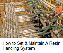
The priority is to maximize movement of powders while minimizing dust exposure.
Article Post: 6/27/2017
DAVID KENNEDY
General Manager, Vac-U-Max
Vacuum conveying systems for powders and other bulk materials involve a starting point and a destination, avoiding many hazards along the way. Powders are transferred from various sources to the processing line using vacuum or negative pressure. The number one advantage of vacuum conveying is dust control, and in the plastics industry, combustible dust is a safety issue.
Vacuum conveying controls dusts by eliminating hand scooping, delivering powders in an enclosed process without fugitive dust. If leaks occur, the leak is inward, unlike positive- pressure systems, which leak outward. Vacuum conveying is preferred by NFPA over positive- pressure conveying. In dilute- phase vacuum conveying, material is entrained within the air stream, with a complementary ratio of air and product.
Related Stories
System controls allow material to convey and discharge on demand, ideal for larger applications requiring movement of bulk materials from larger containers such as bulk bags, totes, railcars, and silos without a lot of manual intervention, reducing frequent container changes.
Typical conveying rates in dilute phase may go up to 25,000 lb/hr, with typical conveying distances of less than 300 ft and line sizes of up to 6-in. diam.
For smaller “up-and-in” conveying applications with conveying rates of less than 0.25 ft3/min, conveying line sizes start at 1.25 in. diam.
Typical conveying rates in dilute phase may go up to 25,000 lb/hr, with typical conveying distances of less than 300 ft and line sizes of up to 6-in. diam.
For smaller “up-and-in” conveying applications with conveying rates of less than 0.25 ft3/min, conveying line sizes start at 1.25 in. diam.
To properly design a pneumatic conveying system, it is important to define the following 10 key criteria in your process:
1. KNOW YOUR BULK DENSITY
As a first step, it is important to know more about the powder that is being conveyed, specifically its bulk density. This is typically described in pounds per cubic feet (PCF) or grams per cubic centimeter (g/cc). This is a key factor in calculating the size of the vacuum receiver.
For example, lighter-weight powders need larger receivers in order for the material to fall out of the air stream. Bulk density of the material is also a factor in calculating the size of the conveying line, which in turn determines the vacuum producer and conveying velocity. Higher-bulk- density materials require faster transport velocity.
For example, lighter-weight powders need larger receivers in order for the material to fall out of the air stream. Bulk density of the material is also a factor in calculating the size of the conveying line, which in turn determines the vacuum producer and conveying velocity. Higher-bulk- density materials require faster transport velocity.
2. KNOW YOUR CONVEYING DISTANCE
Conveying distances comprise both horizontal and vertical factors. A typical “up-and-in” system offers a vertical lift from floor-level, conveying up to a receiver over an extruder or loss-in-weight feeder. It is important to know the number of 45° or 90° sweep elbows.
“Sweep,” in general, refers to a large centerline radius that is typically 8-10 times the diameter of the tube itself. It is important to keep in mind that one sweep elbow is equivalent to 20 ft of linear tubing. For example, 20 ft vertically plus 20 ft horizontally and two 90° elbows equals at least 80 ft of conveying distance.
Reducing the number of elbows in your system should be an important goal. Powders do not flow like liquids, and vacuum conveying systems should minimize the number of back-to-back elbows. If vertical vacuum conveying runs exceed 12-15 ft in batch mode, the material in that line will stop conveying and fall back down. For this scenario, it is important to design a “line-clearing valve” to make sure that the vertical leg is clear before the batch process stops.
3. KNOW YOUR CONVEYING RATE
When calculating conveying rates, it is important to know how many pounds or kilograms per hour will be conveyed. Additionally, define whether the process is batch or continuous. For example, if a process requires conveying 2000 lb/hr of product, but the batch process requires conveying 2000 lb every 5 min for 1 hr, this really amounts to 24,000 lb/hr. This is the difference between 2000 lb in 5 min vs. 2000 lb over a 60-min period. It is important to know the demands of the process in order to properly size the system to determine the conveying rate.
4. KNOW YOUR BULK MATERIALS CHARACTERISTICS
In the plastics industry, there are many different bulk material characteristics, particle shapes, and sizes.
Powders can be fine, cohesive, or floodable. Other characteristics include pastilles, pellets, flakes, granules, and so on. Understanding particle size and size distribution is very important when sizing the receiver and filter assembly, for either mass-flow or funnel-flow distribution.
Other considerations include defining whether the material is free-flowing, abrasive, or combustible; whether it absorbs moisture; and whether there potentially could be chemical compatibility issues with conveying hoses, gaskets, filters, or process equipment.
Additional characteristics include materials that are “smoky” like talcum powder, which has a high fines content, requiring more filter area. For non- free-flowing materials with a high angle of repose, special considerations need to be given to the receiver design and discharge valve.
5. KNOW HOW YOU RECEIVE THE RAW MATERIALS
When designing a vacuum-conveying system, it is important to clearly define how the materials are received and introduced to the process. There are many ways of introducing materials into a vacuum- conveying system; some are more manual, while others are more suitable to automation—and all require attention to control dust.
Material can be received in paper bags, fiber drums, barrels, bulk bags, super sacks, rigid intermediate containers, silos, day bins, railcars, bulk trucks, or upstream process equipment. To maximize dust control, bulk-bag unloaders incorporate enclosed vacuum- conveying lines, and bag-dump stations integrate dust collectors. Material is conveyed from these sources by filter receivers and then conveyed to the process.
6. KNOW YOUR UPSTREAM PROCESS
To properly design a vacuum conveying system, you must define the upstream process that is supplying the material. Find out if the material is coming from a loss-in-weight feeder, volumetric feeder, mixer, reactor, extruder hopper, or any other equipment used to move material.
These all influence the conveying process. Additionally, the frequency of material coming out of these vessels, whether batch or continuous, affects the conveying process and how the material will behave when it comes out of the pro- cess. Upstream equipment affects downstream equipment. It is important to know everything about the source.
These all influence the conveying process. Additionally, the frequency of material coming out of these vessels, whether batch or continuous, affects the conveying process and how the material will behave when it comes out of the pro- cess. Upstream equipment affects downstream equipment. It is important to know everything about the source.
7. KNOW YOUR HEADROOM REQUIREMENTS
This is an important consideration when installing equipment in an existing plant. What may have been designed for manual operation may not offer enough room for an automated process.
Even the smallest conveying system for powder handling will require at least 30 in. of head- room over your pro- cess, taking into consideration maintenance requirements for filter access, discharge-valve inspection, and access to equipment below the conveyor.
Applications requiring high throughput rates, which require large headroom, can use a filterless vacuum receiver. This approach allows some carryover dust to pass through the receiver, which is collected in another ground-level filtered vessel. Scaling valves or positive-pressure systems may also be a consideration for headroom requirements.
8. IS YOUR PROCESS BATCH OR CONTINUOUS?
It is important to define the type of operation that you are feeding: batch or continuous. For example, small conveyors discharging into a surge bin is a batch process. Know whether a batch of material will be received in the process via a feeder or an intermediate hopper, and whether your conveying process can handle the surge of material from a batch.
Alternatively, vacuum receivers may use feeders or rotary valves to meter the material directly into the process—that’s continuous conveying. Or, material can be conveyed into the receiver and discharged at the end of the conveying cycle in a metered way.
Extrusion applications typically utilize both batch and continuous operation, feeding materials directly into the mouth of the extruder.
Extrusion applications typically utilize both batch and continuous operation, feeding materials directly into the mouth of the extruder.
9. KNOW YOUR GEOGRAPHIC OR ATMOSPHERIC CONDITIONS
Geographic and atmospheric considerations are important design considerations, particularly where altitude plays an important part in sizing the system.
The higher the altitude, the more air is required to convey the material. Additionally, consider plant environmental conditions and temperature/humidity control. Certain powders that are hygroscopic can have discharge problems on humid days.
The higher the altitude, the more air is required to convey the material. Additionally, consider plant environmental conditions and temperature/humidity control. Certain powders that are hygroscopic can have discharge problems on humid days.
Materials of construction are a very important consideration in the design and functionality of a vacuum conveying system.
The focus is on product-contact surfaces, which are typically all metallic—plastics are not used for reasons of static control and contamination. Will your process mate- rials be contacting coated carbon steel, stainless steel, or aluminum? Carbon steel is available with various coatings, but those coatings can deteriorate or degrade in use.
For food- and medical- grade plastics processing, 304 or 316L stainless steel is the choice— no need for coatings— with a specified level of polish for ease of cleaning and avoiding contamination.
Maintenance and quality-control personnel care deeply about their equip- ment’s materials of construction.


Comentários
Enviar um comentário